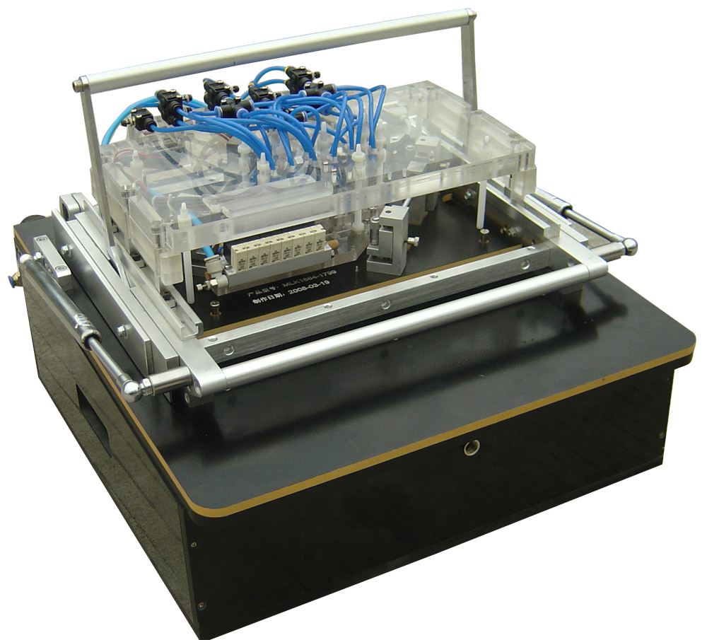
#Circuit board test fixture pdf
The test fixtures are designed as interchangeable kit systems, are connected to an existing test system, and operated with exchangeable kits that are specially designed for the electronic assembly to be tested. PDF Designed and manufactured set of measuring test fixtures for printed circuit board (PCB) materials research and characterization is described in. It will have a main connector that interfaces to. When the PCB board is powered on, obtain the typical values such as the voltage value and current value of the test circuit to observe the test. Connect the pad or test point on the PCB board with a metal probe.

The principle of the PCBA test fixture is very simple. The production of a consumer product that includes a microcontroller on a printed circuit board (PCB) with supporting hardware necessitates thorough testing. Test fixtures of MA 32xx series are suitable for contacting electronic units such as printed circuit boards (PCBs) with high quantities (mass testing) and a large number of versions. The In-circuit test fixture is required to interface the main tester with the particular board under test. PCBA test fixture principle and manufacturing method. The fixture holds the PCB in place over spring-loaded probes.


A single test fixture saves test time and capital expenditure, reducing the potential for errors and damage caused by excessive board handling.
#Circuit board test fixture manual
Manual interchangeable kit test fixtures for mass testing Functional testing of printed circuit boards (PCB) is typically done with a bed of nails fixture. A logical approach combines In-Circuit Testing (ICT) and Functional Testing (FBT) into a single-stage, when possible, to achieve higher fault coverage that may not be possible with ICT-only tests.


 0 kommentar(er)
